Activated sludge is a biological wastewater treatment process where aerobic microorganisms remove dissolved organic pollutants from sewage or industrial effluent. The process treats wastewater effectively, but it also generates waste activated sludge, known as WAS. This excess biological sludge must be thickened, dewatered, stabilized, dried, reused, or disposed of through an approved route.
For plant teams, the real question is not only “Is my activated sludge system treating wastewater?” It is also “What happens to the sludge it produces every day?”
What is activated sludge?
Activated sludge is a suspended-growth biological treatment process used in municipal STPs and industrial ETPs. In this process, microorganisms remain suspended in an aeration tank and consume biodegradable organic matter from wastewater.
The word “activated” refers to the active biological floc, not a chemical additive. This floc contains bacteria, protozoa, and other microorganisms that convert organic pollutants into carbon dioxide, water, and new biomass.
That new biomass becomes sludge. Some of it is returned to the aeration tank to maintain the biological population. The excess is removed as waste activated sludge.
For a broader sludge basics page, you can also read what is sludge.
Activated sludge process in simple steps
A typical activated sludge system has four main stages.
| Stage | What happens | Why it matters |
|---|---|---|
| Primary treatment | Screened wastewater or primary clarified wastewater enters the biological stage | Reduces grit, settleable solids and load on the aeration tank |
| Aeration tank | Wastewater mixes with return activated sludge and oxygen | Microorganisms consume BOD and form biological floc |
| Secondary clarifier | Mixed liquor settles by gravity | Treated water separates from biological sludge |
| Sludge return and wasting | Part of settled sludge returns as RAS, excess sludge leaves as WAS | Maintains process balance and controls sludge age |
In day-to-day plant operation, the aeration tank and secondary clarifier must be treated as one connected biological system. If aeration, MLSS, RAS rate, wasting rate, or clarifier performance goes out of balance, the effluent quality and sludge quality both suffer.
RAS and WAS: the two sludge streams operators must understand
Activated sludge plants produce two important sludge streams.
Return Activated Sludge (RAS) is the settled biological sludge returned from the secondary clarifier to the aeration tank. It maintains the microorganism population required for treatment.
Waste Activated Sludge (WAS) is the excess biological sludge removed from the system. It controls sludge age, MLSS concentration, F:M ratio, oxygen demand, settling behavior, and sludge production.
If WAS is not removed properly, the plant carries too much old biomass. If too much WAS is removed, the aeration tank may lose active biology and fail during shock loads.
This is why sludge wasting is not only a disposal activity. It is a process-control decision.
Key activated sludge design and control parameters
Activated sludge design should always be checked by a wastewater process engineer. The ranges below are practical starting references, not final design values for every ETP or STP.
| Parameter | Practical operating reference | Why it matters |
|---|---|---|
| MLSS | Often 2,000 to 4,000 mg/L in many conventional systems | Maintains biomass concentration for organic removal |
| MLVSS | Organic fraction of MLSS | Better indicator of active biological mass |
| F:M ratio | Commonly around 0.2 to 0.5 kg BOD/kg MLVSS/day for conventional systems | Shows balance between food load and microorganisms |
| SRT or sludge age | Often 3 to 15 days, higher for nitrification | Controls nitrification, sludge stability and WAS generation |
| DO in aeration | Often around 2 mg/L or higher depending on process need | Low DO can cause odour, bulking and incomplete treatment |
| pH | Usually maintained near neutral range | Microbial activity falls when pH moves outside design range |
| RAS rate | Site-specific, often controlled against blanket level and MLSS | Maintains biomass without overloading clarifier |
| SVI | Used to judge settling behavior | High SVI indicates poor settling or bulking risk |
For process-control references, operator manuals commonly treat MLSS, MLVSS, SRT, F:M ratio, sludge quality, and sludge wasting rate as linked variables, not isolated numbers.


Why SRT is one of the most important activated sludge controls
SRT, also called sludge age or MCRT, tells how long microorganisms remain in the system.
A short SRT can reduce excess sludge age but may wash out slow-growing nitrifying organisms. A long SRT can improve biological stability and nitrification, but it may also create older sludge that can be harder to dewater.
In practical terms:
| SRT condition | Common plant impact |
|---|---|
| Too low | Biomass loss, weak treatment, poor nitrification risk |
| Too high | Old sludge, fine floc, possible foaming or harder dewatering |
| Stable and matched to load | Better biological control, predictable WAS generation |
When I review sludge drying requirements from an activated sludge plant, I do not start only with dryer capacity. I first ask how the plant controls SRT, how much WAS is wasted daily, whether the sludge is stabilized, and what moisture comes out of the dewatering system.
Activated sludge configurations
Different activated sludge configurations produce different sludge characteristics.
| Configuration | Where it is commonly used | Sludge handling note |
|---|---|---|
| Conventional activated sludge | Municipal STPs and large ETPs | Needs regular WAS wasting and separate sludge handling |
| Complete mix | Variable industrial wastewater loads | Better shock-load mixing, but sludge production still needs control |
| Extended aeration | Smaller STPs and package plants | Produces more stabilized biological sludge, but dewatering can still be difficult |
| SBR | Batch-based ETP/STP systems with limited space | WAS is removed by cycle control and requires planned handling |
| MBR | Space-constrained plants needing high-quality effluent | High MLSS operation, membrane sludge may need careful dewatering |
If your page cluster covers STP and wastewater plant topics, link this page with STP sludge treatment and wastewater treatment plant.
Common activated sludge problems and what they indicate
Activated sludge problems usually show up first in the clarifier, foam layer, sludge blanket, DO trend, or effluent TSS.
| Symptom | Likely cause | Operator check |
|---|---|---|
| Bulking sludge | Filamentous growth, low DO, nutrient imbalance, high F:M | Check DO, F:M, SVI, microscopic sludge condition |
| Pin floc | Old sludge, low F:M, toxicity, over-aeration in some cases | Check SRT, MLSS, clarifier overflow and toxicity history |
| Rising sludge | Denitrification in clarifier or long sludge blanket age | Check sludge blanket, RAS rate, WAS rate and nitrate conditions |
| Foaming | Nocardia, Microthrix, oils, grease, surfactants or low F:M | Check influent changes, oil and grease, SRT and surface foam pattern |
| High effluent TSS | Poor settling, hydraulic overload or clarifier problem | Check clarifier loading, sludge blanket and RAS withdrawal |
| Odour from sludge | Septic sludge, poor DO or delayed sludge removal | Check sludge retention in clarifier and sludge holding tank |
For a more focused troubleshooting page, use the internal support article on activated sludge system troubleshooting.
What happens to waste activated sludge?
Waste activated sludge is excess biological biomass removed from the system to maintain process balance. It is usually dilute when first wasted and needs further processing before economical disposal.
A practical WAS handling chain looks like this:
| Step | Purpose | Typical plant concern |
|---|---|---|
| Thickening | Increase solids concentration and reduce volume | Gravity thickener, DAF or mechanical thickening performance |
| Stabilization | Reduce volatile solids, odour and biological activity | Aerobic digestion, anaerobic digestion or extended aeration |
| Dewatering | Convert dilute sludge into cake | Polymer selection, filter press/centrifuge output moisture |
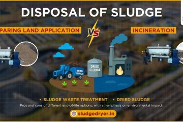
| Drying | Reduce remaining moisture for disposal, reuse or co-processing | Thermal load, final moisture target, odour/off-gas management |
| Disposal or reuse | Send to authorized route or approved beneficial use | Sludge classification, heavy metals, pathogen limits, calorific value |
Activated sludge is usually harder to dewater than primary or chemical sludge because biological floc holds water strongly. This is why a filter press, centrifuge, or belt press may still leave a wet cake that is expensive to transport.
To support this cluster, link this section to sludge dewatering techniques and sludge thickener fundamentals.
Why biological WAS often needs drying after dewatering
Dewatering removes free water. Drying removes much more of the remaining bound and capillary moisture. This difference matters because biological sludge can leave a dewatering unit with high residual moisture.
If wet biological cake is directly transported, plants face:
- higher transport weight
- more storage space
- odour and hygiene issues
- difficult manual handling
- higher disposal frequency
- inconsistent downstream reuse options
A sludge dryer helps reduce moisture further, making the material easier to handle, store, transport, and route for approved disposal or reuse.
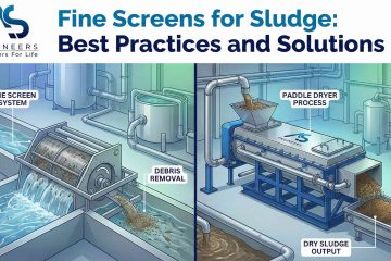
AS Engineers’ paddle dryer design uses indirect heating from hollow shafts and jacket surfaces, self-cleaning wedge-shaped paddles, and continuous mixing to handle sludge, paste, cake, granules and similar feed forms. AS Engineers source material also lists sewage treatment plant sludge and biosludge among materials handled using paddle dryer technology.
For deeper equipment selection, use guide to sludge dryers and thermal sludge drying system guide.
Activated sludge and regulatory responsibility in India
Activated sludge plants are usually installed to meet treated wastewater discharge limits. For industrial effluent, CPCB’s general standards under Schedule VI include limits such as suspended solids of 100 mg/L and BOD of 30 mg/L for inland surface water discharge, subject to the applicable category and consent condition.
Plant teams should not rely only on general national limits. Always verify:
- latest CTO/CTE consent condition
- applicable SPCB direction
- discharge destination
- municipal, industrial, CETP or ZLD requirement
- hazardous or non-hazardous sludge classification
- authorized disposal route
- pathogen and heavy metal requirements for any reuse route
For hazardous or industrial sludge routes, connect this page with CPCB hazardous waste disposal guidance and TSDF site standards.
Where paddle dryer fits in the activated sludge treatment chain
A paddle dryer does not replace the activated sludge process. It fits after biological treatment, thickening and dewatering.
The usual sequence is:
Wastewater treatment → WAS wasting → thickening → stabilization → dewatering → sludge drying → approved disposal or reuse
A paddle dryer-based system is most useful when:
| Plant condition | Why drying helps |
|---|---|
| Daily WAS cake generation is high | Reduces transport and disposal load |
| Dewatered cake remains too wet | Further moisture reduction improves handling |
| Disposal distance is high | Lower mass reduces logistics pressure |
| Storage area is limited | Dried sludge occupies less space than wet cake |
| Sludge is planned for co-processing or controlled reuse | Moisture target can be matched to end-use requirement |
| Monsoon handling is difficult | Dried output is easier to store than wet cake |
For AS Engineers’ wider technical explanation, add contextual support to paddle dryers for sludge drying and thermal drying of sludge with paddle sludge dryers.
Fit and no-fit guidance for drying waste activated sludge
| Situation | Dryer fit |
|---|---|
| WAS is already thickened and dewatered into manageable cake | Good fit for thermal drying review |
| WAS is still liquid at 98 to 99% moisture | Drying directly is usually inefficient, thicken/dewater first |
| Sludge classification is unclear | Do lab characterization before equipment selection |
| End-use route is not finalized | Define disposal, co-processing, fertilizer or landfill route first |
| Cake moisture varies widely | Dryer sizing should use worst-case moisture, not ideal lab result |
| Sludge has toxic, corrosive or hazardous contaminants | MOC, off-gas and safety review are required before recommendation |
The most common mistake is buying drying equipment before understanding sludge chemistry, daily sludge quantity, inlet moisture, final moisture target, and disposal route.
RFQ checklist for activated sludge drying projects
Before asking for a sludge dryer quotation, collect these inputs:
| RFQ input | Why AS Engineers needs it |
|---|---|
| Plant type | STP, ETP, CETP, MBR, SBR or extended aeration |
| Flow and loading | MLD, BOD, COD, TSS and operating hours |
| WAS generation | kg/day dry solids and wet sludge quantity |
| Existing thickening method | Gravity thickener, DAF or mechanical thickener |
| Existing dewatering unit | Filter press, centrifuge, screw press or belt press |
| Cake moisture | Actual measured moisture, not only design assumption |
| Polymer program | Polymer type, dose and cake consistency |
| Final moisture target | Disposal, storage, co-processing or reuse requirement |
| Heating medium | Steam, thermic fluid, hot water or other site utility |
| Sludge classification | Municipal, biological, hazardous, non-hazardous or mixed |
| MOC concern | Chloride, pH, corrosive constituents, abrasive solids |
| Off-gas requirement | Odour control, scrubber, condenser, cyclone or bag filter |
| Site constraints | Space, height, access, power, fuel and maintenance access |
At AS Engineers, we review these inputs before recommending dryer configuration, heating medium, feeding arrangement, pollution-control equipment and product handling system.
Common mistakes in activated sludge and WAS management
Running the aeration tank properly but ignoring sludge disposal.
A plant can meet effluent limits and still struggle with daily biological sludge handling.
Using only MLSS as the control number.
MLSS is important, but SRT, F:M, DO, SVI, RAS and WAS rate must be read together.
Assuming dewatered sludge is already dry enough.
Dewatering and drying are different stages. Filter cake can still carry high moisture.
Sizing a dryer on ideal cake moisture.
Use actual site moisture data, monsoon variation, polymer performance and worst-case feed condition.
Treating STP sludge and industrial ETP sludge the same.
Municipal biological sludge, industrial biological sludge, chemical sludge and hazardous sludge need different handling and disposal decisions.
Claiming reuse before testing.
Agriculture, fuel, brick or cement use depends on sludge analysis, regulations, calorific value, heavy metals, pathogen control and receiving facility approval.
FAQs
What is activated sludge in wastewater treatment?
Activated sludge is a biological treatment process where aerobic microorganisms are suspended in an aeration tank to consume organic pollutants from wastewater. The microorganisms form biological floc, settle in a secondary clarifier, and part of the settled sludge is returned to the aeration tank.
What is the difference between RAS and WAS?
RAS means return activated sludge. It is sent back to the aeration tank to maintain the biological population. WAS means waste activated sludge. It is the excess sludge removed from the system to control sludge age, MLSS and process balance.
Why is waste activated sludge difficult to dewater?
Waste activated sludge is biological sludge. Its floc structure holds water strongly, so it may not release moisture as easily as primary or chemical sludge. Polymer conditioning, sludge age, digestion, and dewatering equipment condition all affect cake moisture.
Can activated sludge be dried in a paddle dryer?
Yes, dewatered biological sludge from activated sludge systems can be evaluated for paddle dryer-based thermal drying. The right configuration depends on inlet moisture, cake consistency, final moisture target, sludge classification, heating medium, MOC and off-gas handling requirement.
Does drying activated sludge make it suitable for reuse?
Drying improves handling and reduces moisture, but reuse depends on sludge analysis and approvals. Dried sludge may be considered for agriculture, fuel, cement, bricks or authorized disposal only when pathogen, heavy metal, calorific value and regulatory requirements are satisfied.
Conclusion
Activated sludge is one of the most important biological treatment processes in STPs and ETPs, but the process is incomplete without a clear waste activated sludge management plan. MLSS, SRT, F:M ratio, DO, RAS and WAS wasting control the biology. Thickening, stabilization, dewatering and drying control the sludge burden after treatment.
If your activated sludge plant produces biological sludge every day, do not evaluate only the aeration tank. Review the complete sludge chain from WAS generation to final disposal. For sludge dryer selection, share your WAS quantity, dewatered cake moisture, final moisture target, heating medium, sludge classification and site constraints so the dryer system can be reviewed against real operating conditions.